Instruments
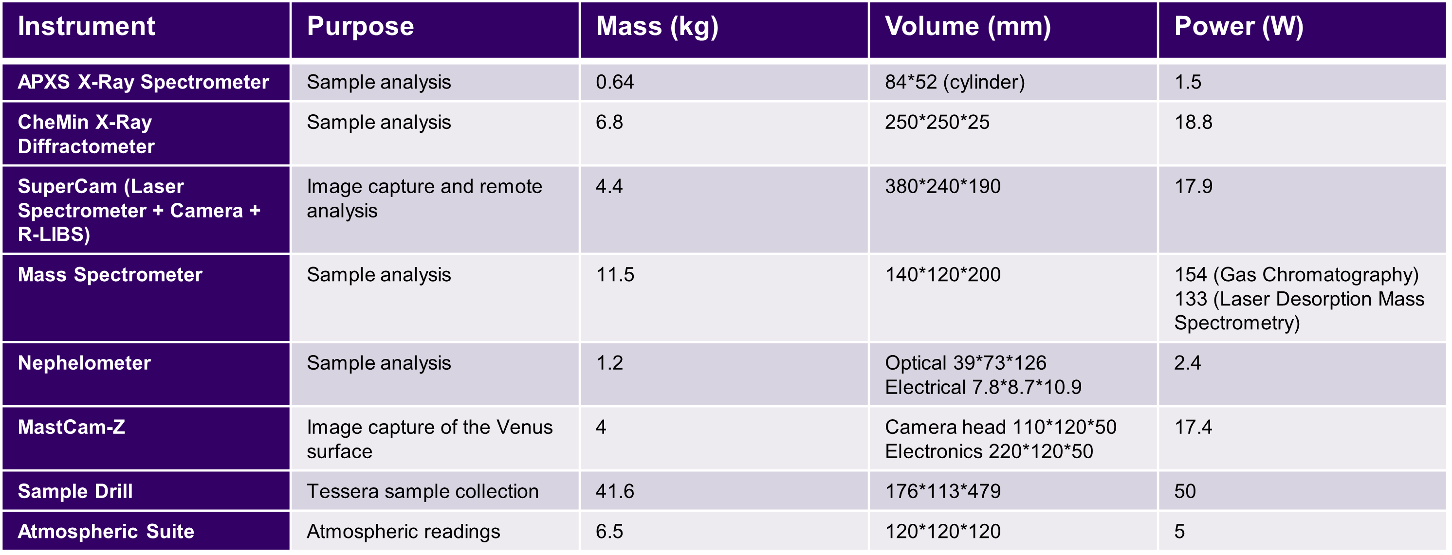
The approach we took to design the lander was to initially figure what instruments we would require to meet our scientific objectives. These are listed in the table along with their mass, dimension and power requirement. Knowing these quantities allowed us to design the lander to fit these. Most of them will be used for sample analysis such as the Spectrometers. The lander will also have a drill for sample collection.
Thermal & Power System
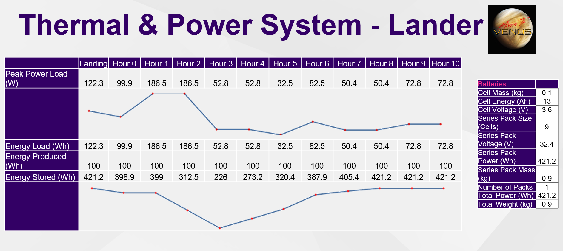
This is the power budget for the Lander. We considered a cycle of 10 hours whereby instruments will be operating at given times. Communications, data processing and control and monitoring will be running every hour. During hours 1 and 2 for example the mass spectrometer will be running. From this schedule and peak power loads we decided that our primary power system (Stirling Engine) would produce 100W and any extra power required at times of peak power load would be provided by batteries. A total of 9 cells will be used weighing under a 1kg and providing a total of 420 Wh.
Descent & Landing
 Parachutes
- Dimensions: 1.9m Diameter
- Material: Kevlar
- Quantity: 3 Parachutes
- Total Mass: 16.69 kg
- Dimensions: 6.44m Length. 0.005m Diameter
- Material: Zylon
- Quantity: 12 Lines / Parachute
- Total Mass: 7.01 kg
- Dimensions: 0.0064 m3
- Quantity: 3 (1 per parachute)
- Total Mass: 27.39 kg
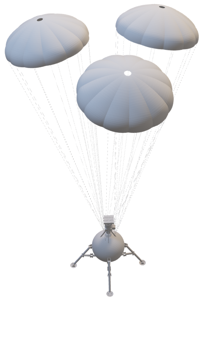
As the lander descends, its terminal velocity is 16.2m/s. This isn’t large but needs to be reduced to approximately 4 m/s for landing therefore, we have used parachutes. For redundancy and better stability, there are 3 ring-sail parachutes, 1.9m diameter each and are made of kevlar due to its high melting point of 500 degrees. Each parachute has 12 lines, 6.44m length and are made of Zylon. This material is very strong with a melting point of 600 degrees. The lines have a diameter of 5mm, 100 times the minimum thickness needed to withstand the load of the lander. Furthermore, the time taken for the lander to reduce from its terminal velocity of 16.2 m/s to 4 m/s, is very short so the lines will not be exposed to the harsh Venus atmosphere therefore, the degradation of the lines will not have an impact. The parachutes will use mortar deployment which is a device that ejects the packed parachute. It is one of the most common deployment devices for spacecraft. It has a mass of 9.13 kg each, totalling to 27.39 kg for the 3 contraptions. This totals to 51.09kg for the descent controls.
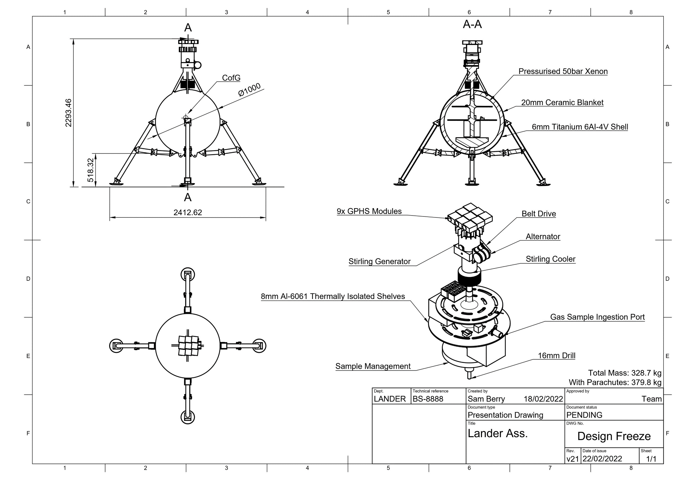
For the legs, they are 1m tall and are attached to the centre of the vessel. This is so the bottom of the sphere is clear from any rocky terrain but the drill can still be used. The large discs-shaped feet on the bottom of the legs are to distribute the weight evenly and so that the lander will not sink into the ground. They are made of titanium with a mass of 22.2kg each, 88.8kg for the four of them.
Systems Diagram
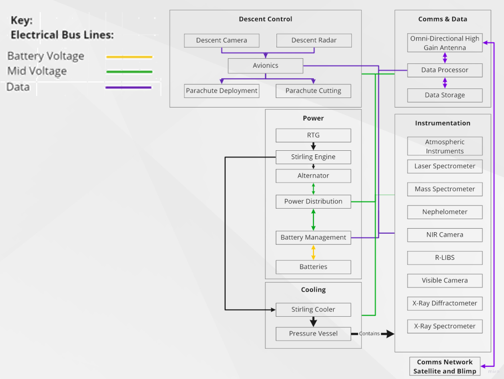 Here we have the System Diagram for the Lander showing the 4 principle systems. The descent control, Communication & Data, Power and the Instrumentation.
In the Descent Control system we have the parachute subsystem and the camera plus radar to aid in choosing a safe landing spot. In the Power system the Stirling Engine with its Radioisotope modules and the batteries are shown. With regards to Comms the links between the omni-directional antenna, data processor and data storage are shown. Finally all instruments are displayed as well.
Here we have the System Diagram for the Lander showing the 4 principle systems. The descent control, Communication & Data, Power and the Instrumentation.
In the Descent Control system we have the parachute subsystem and the camera plus radar to aid in choosing a safe landing spot. In the Power system the Stirling Engine with its Radioisotope modules and the batteries are shown. With regards to Comms the links between the omni-directional antenna, data processor and data storage are shown. Finally all instruments are displayed as well.